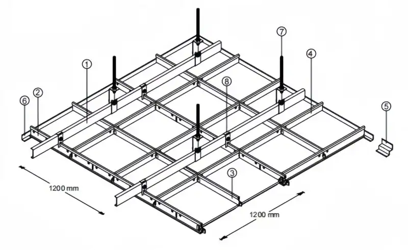
This general installation manual covers modular ceiling tile systems, including, but not limited to, fiberglass, rock wool, and mineral wool ceiling tiles. It applies to both exposed and concealed grid systems.

①Top grid
②Wall moulding
③Main T-grid
④Cross T-grid
⑤”W” Wall angle
⑥”L” Wall angle
⑦Suspension hanger
⑧Suspension rod
Installation tools
Laser level, measuring tape, marker, impact hammer, electric drill, wire cutters, wrenches, aluminum alloy straightedge, utility knife, handsaw, sandpaper, mobile scaffolding, rubber mallet, spirit level, vacuum cleaner, dust mask, safety goggles, gloves, etc.

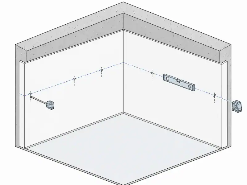
Step 1: Wall marking and positioning
- Use a laser level to mark the ceiling completion elevation line on all four walls, creating a closed loop throughout the room. Keep the horizontal error within 1.5mm. For large-area commercial ceilings, add a horizontal control line every 3m.
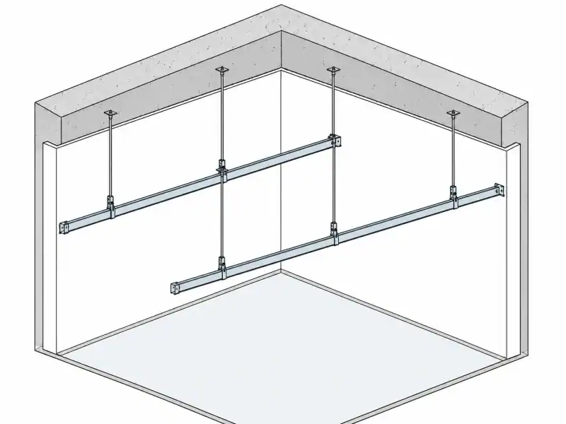
- Mark the hanger point lines on the ceiling: 38 main T-grid spacing 900mm, hanger spacing 900mm, and hanger distance from the main T-grid end no more than 250mm. No additional hangers are needed if the distance from the wall edge is less than 300mm.
- Mark the T-grid lines on the ceiling: strictly follow the 600*600mm grid. Where corners cannot fit a full board, mark the cutting dimensions separately to ensure a symmetrical, aesthetically pleasing grid division throughout the room.

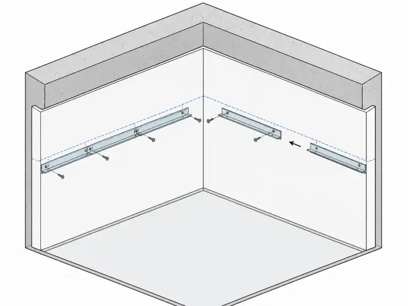
Step 2: L-shaped wall moulding installation
- Fix the L-shaped wall moulding along the wall elevation line. Use a 45° diagonal splice at corners, controlling the splice gap to within 0.5mm. Direct overlap is prohibited to prevent cracking and warping at the finish.
- Use 400mm spacing for solid brick walls and 250mm spacing for hollow brick walls. Fixing screws must be installed within 100mm on both sides of door and window openings to prevent corner sagging.
- Splice the edge joists with staggered overlaps, with an overlap length of no less than 50mm. Seal the overlap with sealant.
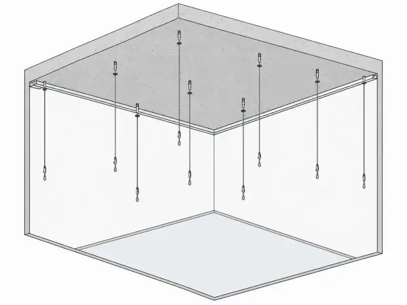
Step 3: Hanger installation
- Drill holes in the ceiling according to the hanger locations, with a hole depth of 55-60mm. Clean the holes of dust, insert M6 expansion bolts, and tap them firmly to ensure secure anchoring.
- Install the M6 threaded hangers, leaving an 80mm adjustment allowance at the bottom of the hanger for later overall leveling. If the hanger length exceeds 1.5m, add a horizontal reverse tie rod to prevent the ceiling from swaying.
- Spray anti-rust paint on the cut surfaces of the hangers to prevent rust.
Step 4: Top grid installation
- Insert the top grid into the hanger rod, initially fix it with nuts, and then insert the top grid into the hanger. Use special extension parts to extend the top grid. Stagger the splicing positions of adjacent top grids by more than 500mm. Splicing on the same section is prohibited.
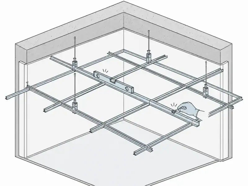
- Using the L-shaped wall moulding elevation on the wall as a reference, level the top grid by pulling a line in both directions. Use a 2m straightedge to check that the flatness error is within 2mm. The height difference throughout the entire room should not exceed 3mm.
- Leave a 3mm expansion gap between the main keel and the wall to allow thermal expansion and contraction and prevent arching.
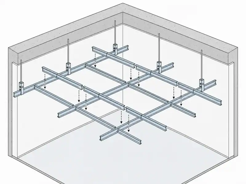
Step 5: Main & cross T-grid installation
- Install the main T-grid perpendicular to the top grid, spaced 600mm apart. Secure it to the top grid with special fasteners. Ensure all fasteners are tight; loose fasteners are not permitted.
- Install the cross T-grid parallel to the short sides, spaced 600mm apart. Overlap the ends with the main T-grid slots. Install an additional cross T-grid at the corners where boards are cut, so that both ends of the cut boards are supported by the grids.
- Align all T-grid joints. Keep exposed grid lines straight, with a straightness error of 2mm along the entire length.
Step 6: Grids inspection
- The grids should be free of looseness or wobbling, and should not shift when manually cranked.
- All hangers and fittings must be complete and secure. Sprinkler systems, smoke detectors, lighting fixtures, and air vents must not be directly fixed to the cross T-grids.
- Equipment weighing >2kg must have a separate, independent hanger fixed to the concrete ceiling. All pipelines within the ceiling should be securely fixed, with no pipelines pressing against the grids.
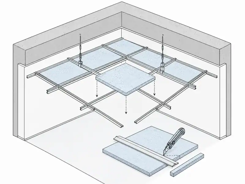
Step 7: Ceiling tiles installation
- Use whole tiles for the central area of the entire room. For wall edges and corners, measure on-site and cut with a utility knife and an aluminum alloy ruler. After cutting, sand the edges to prevent jamming and chipping when inserting into the joists.
- Lay the tiles from the center of the room outwards, first whole boards, then cut the corner boards. Insert the boards directly into the T-grids’ joist slots without screws or glue, relying on the joists’ weight for fixation.
- Keep the gaps between tiles uniform, with a gap width of 1.5mm and a height difference of no more than 1mm. Forcibly squeezing the boards is strictly prohibited to prevent later warping and cracking.
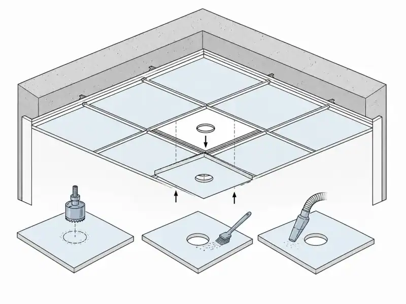
Step 8: Drilling holes and cleaning
- Use a hole saw to drill round holes. Do not cut arbitrarily with a utility knife. Apply edge-trim strips around the drilled holes to prevent tiles from chipping.
- Use a vacuum cleaner to clean the gaps between the joists and the dust on the tiles. Do not wipe the tiles directly with a damp cloth.